Autometer Boost Gauge Wiring Diagram
It shows the components of the circuit as simplified shapes and the capacity and signal associates with the devices. Give us a Call We Love Helping Out.
 Honda S2000 Boost Controller Boost Gauge Mitsubishi Lancer Evolution Wiring Diagram Honda Elektronik Kabel Kabel Listrik Aem Png Pngwing
Voltmeter gauge wiring diagram wiring diagram is a simplified customary pictorial representation of an electrical circuitit shows the components of the circuit as simplified shapes and the facility and signal contacts with the devices.
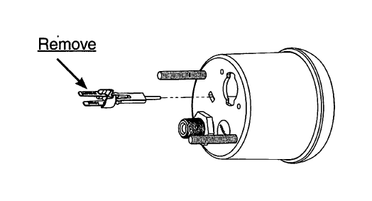
Autometer boost gauge wiring diagram. Connect the red power wire to a switched 12 volt source that maintains power during engine cranking. Another thing you will come across a circuit diagram. Injunction of two wires is generally indicated by black dot on the junction of 2 lines.
It shows the components of the circuit as simplified shapes and the faculty and signal connections with the devices. I did a piggyback fuse and ran an extended wire under the dash to the passenger fuse box. Wiring Diagram arrives with several easy to follow Wiring Diagram Guidelines.
It may be necessary to remove Vehicle Trim andor Kick Panels in order to gain access to the vehicles Fuse Box. However it does not mean connection between the wires. Ad Seriously into Audio Since 1974.
These guidelines will be easy to understand and apply. Autometer Gas Gauge Wiring Diagram wiring diagram is a simplified usual pictorial representation of an electrical circuit. Therell be main lines that are represented by L1 L2 L3 and so on.
In order to test for power reconnect the Negative Battery Terminal. Autometer Boost Gauge Wiring Diagram. Connect ground wire from ground post on gauge to suitable chassis ground.
Its intended to aid all the average person in developing a suitable method. Reconnect negative - battery cable. If the boost gauge is connected to one of these circuits the auto zero function will not work properly and inaccurate readings will result.
How to Install an Auto Meter Pro-Comp Ultra-Lite AirFuel Ratio Gauge - Electric on Your M or wiring diagram for your specific vehicle to learn which wire is the signal. Give us a Call We Love Helping Out. 2-116gauges mount in 2-1 16 diameter hole 2-5 8 gauges mount in 2-58 diameter hole.
Holes and install rubber grommet where pressure or. Oil Pressure Gauges and Kits. Spade on back of gauge.
We are installing an Autometer boost gauge into a second generation 1995-1999 Mitsubishi Eclipse GSX Turbo but your install will be very similar if you do not own this vehicle in question. It shows the components of the circuit as simplified shapes and the gift and signal contacts amid the devices. There are just two things which are going to be present in any Autometer Gauge Wiring Diagram.
Do not connect ohm meter to oxygen sensor or touch wire to ground or power. Northern Virginia USA. Ad Seriously into Audio Since 1974.
Most vehicles break the electrical connection to accessories while the engine is being started. A circuit is generally composed by various components. The first component is emblem that indicate electric component in the circuit.
Autometer Pro Comp Ultra Lite Wiring Diagram Fresh Auto Meter Wiring Autometer Gauge Wiring Diagram. Secure gauge with mounting clamps supplied. After reading through this article you will know How To Install a Boost Gauge in any turbocharged vehicle.
As stated earlier the traces in a Autometer Gauge Wiring Diagram signifies wires. Auto Gauge Boost Gauge Wiring Diagram wiring diagram is a simplified gratifying pictorial representation of an electrical circuit. Wiring Diagram arrives with several easy to follow Wiring Diagram Guidelines.
Autometer Oil Pressure Gauge Wiring Diagram wiring diagram is a simplified adequate pictorial representation of an electrical circuit. Air Fuel Ratio Gauges. Gauges may be mounted in In-dash holes or in Auto Meter custom mounting Solutions.
Be sure that body or mounting flange of sender is grounded to suitable chassis ground. These guidelines will be easy to understand and apply. Awesome- Encouraged in order to my blog site within this time Ill demonstrate regarding autometer gauge wiring diagram.
Using a Test Light locate a Constant 12-volt Power. I found the wiring easy the worst part was running the boost line through the cabin to the engine bay. Pressure Gauges Kits.
Heres a reference for the fuse box. And now this is the first image. Autometer Pyrometer Wiring Diagram wiring diagram is a simplified tolerable pictorial representation of an electrical circuit.
TS mechanical gauge mounted into an ATI pod. Slide the BoostVacuum Line onto the back of the Gauge and secure the supplied clamp. Autometer Pro Comp Ultra Lite Wiring Diagram Fresh Auto Meter Wiring Autometer Gauge Wiring Diagram.
Sometimes the cables will cross. Damage to oxygen sensor will result. It shows the components of the circuit as simplified shapes and the aptitude and signal associates in the midst of the devices.
Its intended to aid all the average person in developing a suitable method. Connect wire from ignition switch to the positive I terminal on the back of gauge. Otherwise the structure wont work as it should be.
Autometer Gauge Wiring Diagram.
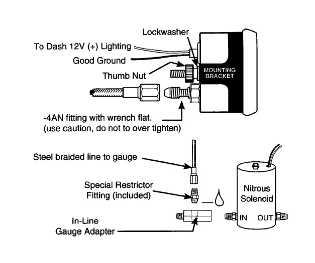 How To Install Auto Meter Hoonigan Boost Vacuum Gauge 30 Psi Mechanical On Your Mustang Americanmuscle
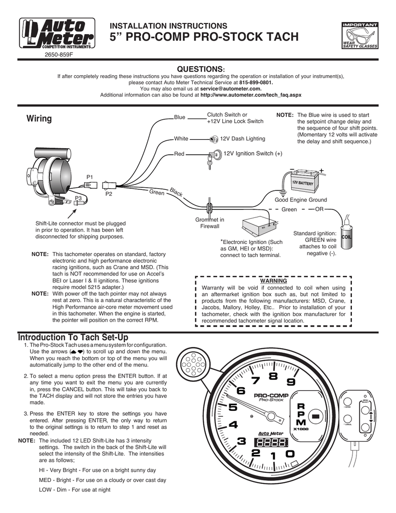 5 Pro Comp Pro Stock Tach Wiring Installation Instructions Manualzz
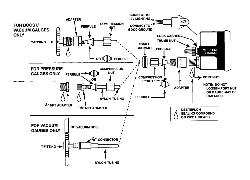 How To Install Auto Meter Hoonigan Boost Vacuum Gauge 30 Psi Mechanical On Your Mustang Americanmuscle
 2 1 16 Boost 0 15 Psi Mechanical Ultra Lite
 Auto Meter 6858 Installation Instructions Manualzz
 Diagram Boost Gauge Wire Diagram Full Version Hd Quality Wire Diagram Ladderdiagram Antichemurasorrento It
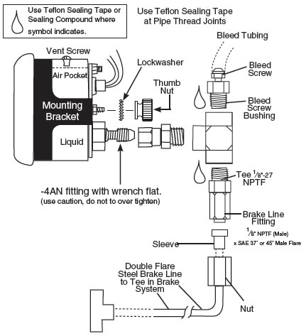 How To Install An Auto Meter Pro Comp Ultra Lite Boost Vac Gauge Mechanical On Your 1979 2012 Mus Americanmuscle
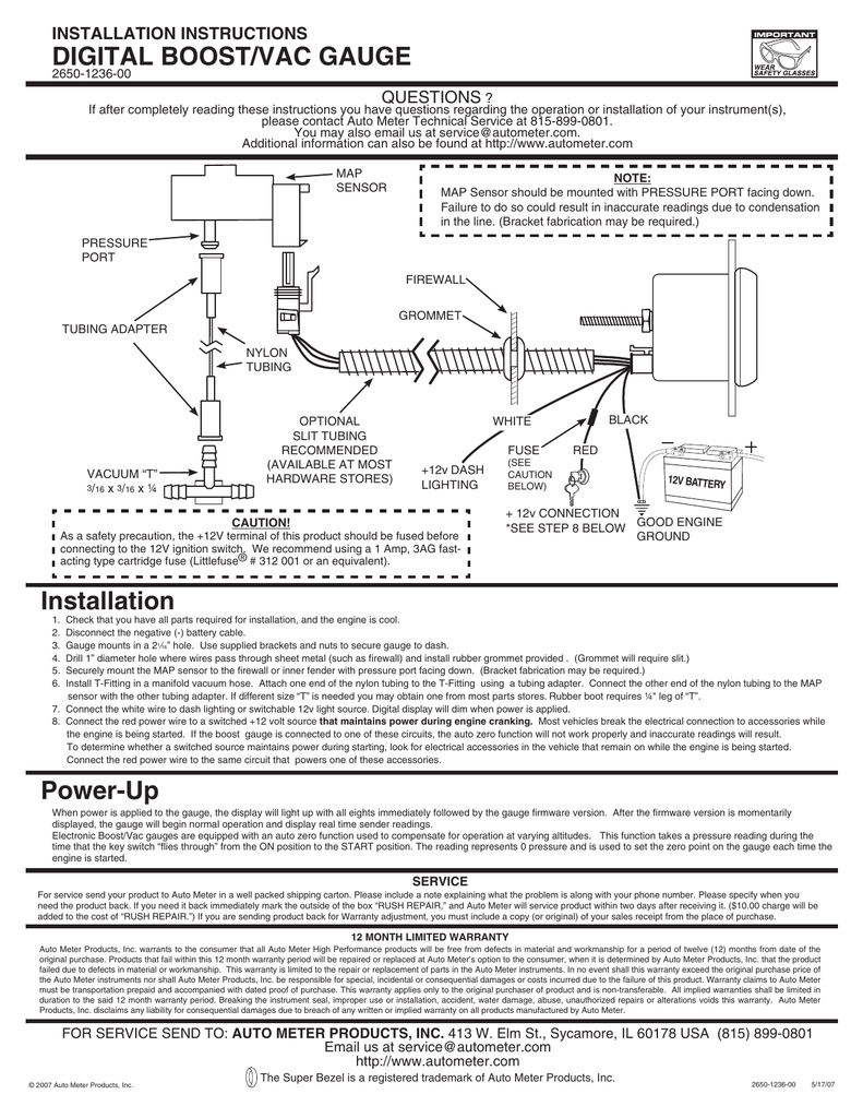 Digital Boost Vac Gauge Installation Instructions 2650 1236 00 Manualzz
 2 1 16 Boost 0 35 Psi Mechanical Sport Comp
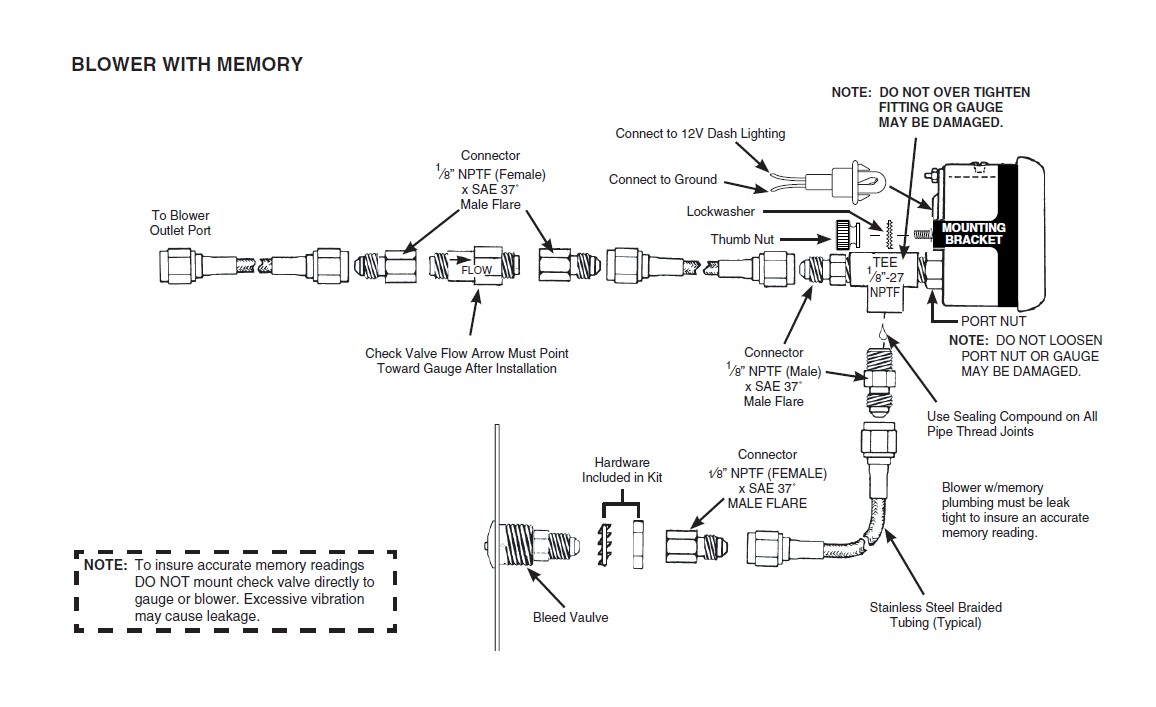 How To Install Auto Meter Factory Match Boost Gauge 0 100psi Mechanical 09 17 Ram 1500 On Your Dodge Ram Americantrucks
 Auto Gauge Wiring Diagram Cikeri
 Installation Of Auto Meter Cobalt Wideband Air Fuel Gauge Installation Of Auto Meter Cobalt Wideband Air Fuel Gauge Pdf Pdf4pro
 Addco 2 52mm 7 Color Led Smoke Face Car Meter Boost Gauge Water Temperature Oil Pressure Volt Tachometer Meter Buy Boost Gauge Water Temperature Oil Pressure Product On Alibaba Com
 2 1 16 Pyrometer 0 1600 F Stepper Motor Gen 3 Dodge Factory Match
 How To Install Auto Meter Hoonigan Boost Vacuum Gauge 30 Psi Mechanical On Your Mustang Americanmuscle
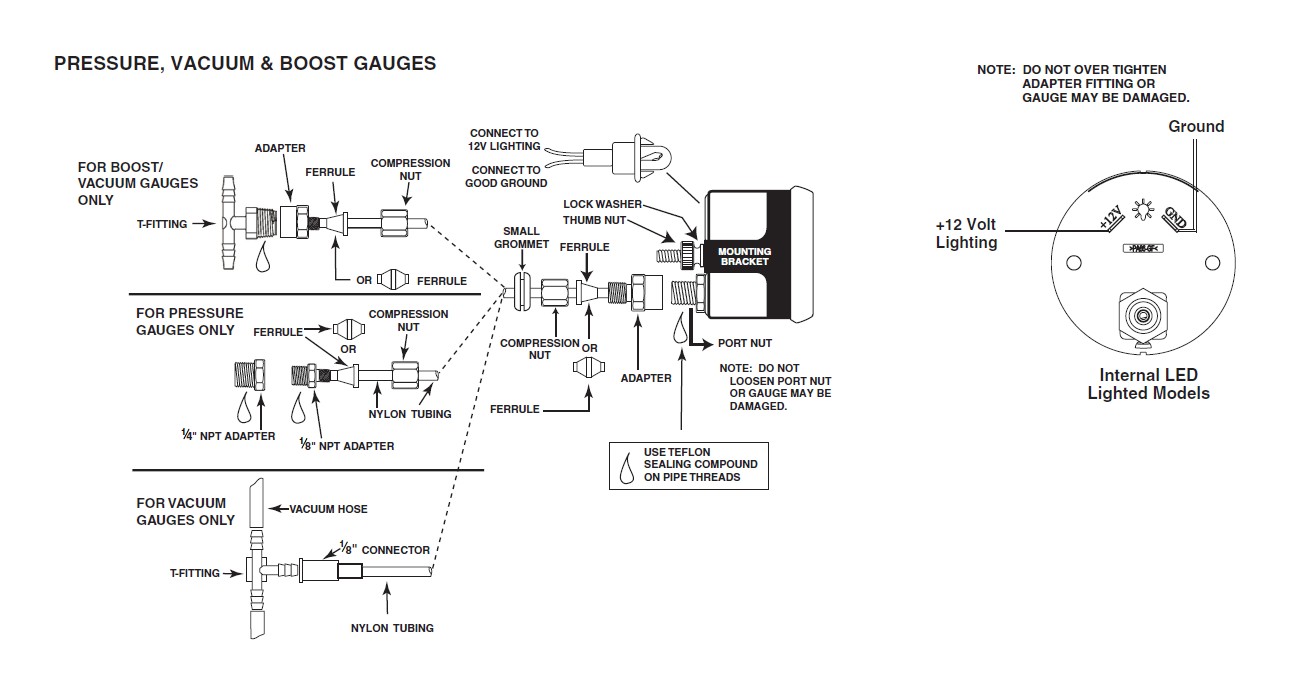 Diagram Auto Meter Phantom Wiring Diagram Full Version Hd Quality Wiring Diagram Diagramofbrain Salutesolidarieta It
How To Install Vdo Turbo Boost Vacuum Gauge I Club The Ultimate Subaru Resource
 Digital Boost Vac Gauge Installation Instructions 2650 1236 00 Manualzz
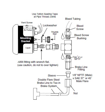 How To Install Auto Meter Factory Match Boost Gauge 0 35 Psi Mechanical On Your Dodge Ram Americantrucks
No comments for "Autometer Boost Gauge Wiring Diagram"
Post a Comment